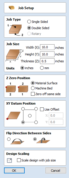
Job Setup - Double Sided
The Job Setup form is displayed whenever a new job is being created, or when the size and position of an existing job is edited.
In most cases a new job represents the size of the material the job will be machined into or at least an area of a larger piece of material which will contain the part which is going to be cut. Clicking OK creates a new empty job, which is drawn as a gray rectangle in the 2D View. Dotted horizontal and vertical Grey lines are drawn in the 2D design window to show where the X0 and Y0 point is positioned.
Job Type
Single Sided job type should be used when design only requires the material to be cut from one side. This is the simplest type of job to design and machine.
Double Sided Job type is useful when it is desired to cut both sides of your material. Aspire allows you to visualise and manage the creation and cutting process of both sides of your design within a single project file.
Rotary job type enables the use of a rotary axis (also called a 4th axis or indexer).Aspire will provide alternative visualisation, simulation and tools appropriate for rotary designs.
Job Size
This section of the form defines the dimensions of the material block you will be using for your project in terms of width (along the X axis), height (along the Y axis) and thickness (along the Z axis).
It also allows you to select which units of measurement you prefer to design in - either inches (Imperial/English) or millimeters (Metric).
Cut2D Desktop only supports job sizes up to a maximum of 25 inches square without tiling.
You can cut jobs larger than this limit but you will need to use the Toolpath Tiling feature to cut the job in sections.
Z Zero Position
Indicates whether the tip of the tool is set off the surface of the material (as shown in the diagram) or off the bed / table of the machine for Z = 0.0.
Zero off same side
This option allows Z Zero to reference the same physical location, regardless whether material is flipped or not
XY Datum Position
This datum can be set at any corner, or the middle of the job. This represents the location, relative to your design, that will match the machine tool when it is positioned at X0, Y0. While this form is open, a red square is drawn in the 2d view to highlight the datum's position.
Use Offset
This option allows the datum position to be set to a value other than X0, Y0.
Flip Direction Between Sides
This section gives choice between horizontal and vertical flipping when changing machining side. Aspire uses that information to correctly manage the alignment of the geometry relating to each side.
Design Scaling
When editing the Job Size parameters of an existing job, this option determines whether any drawings you have already created will be scaled proportionally to match the new job dimensions. If you wish to preserve the existing size of your drawings, even after the job size has changed, leave this option unchecked. With this option checked, your drawings will be re-sized to remain in the same proportion and relative position within your new material extents when you click